
Core Controller
| Component | Example Model | Purpose |
|---|---|---|
| MCU or SBC | Raspberry Pi 4 / Pi Zero 2 | Main processor, runs Python API/logic |
| ESP32 (if low-power) | Alt: For battery-based or Wi-Fi-only ops |
Security & Sensor Modules
| Component | Example Model | Purpose |
|---|---|---|
| TPM Module | Infineon SLB 9670 (SPI) | Secure key storage, attestation |
| Temp/RF sensor | MLX90640 or RF Explorer | Detect overheating or suspicious RF activity |
| Bus activity monitor | INA219 / Logic Analyzer | Detect abnormal power/spike patterns on USB or I2C |
| Uptime watchdog | PMIC with GPIO (e.g., MAX706) | Reset device on tamper or hang |
Network & Scan Interfaces
| Component | Example Model | Purpose |
|---|---|---|
| Wi-Fi + BLE Module | Built-in to Pi / ESP32 | Discover local devices + BLE beacons |
| RFID/NFC Reader | PN532 | Tag scan-in/out, device identification |
| USB Analyzer | USB2534 / inline sniffer | Detect USB implants or rogue traffic |
Trust Input & Auth Control
| Component | Example Model | Purpose |
|---|---|---|
| Physical QR scanner | Arducam Mini or PiCam | Read QR-based validator credentials |
| Fingerprint scanner | GT521F32 / R307 | Validate admin/operator access |
| Tamper switch | Spring pin or microswitch | Detect case opening or unauthorized access |
Storage & Logging
| Component | Example Model | Purpose |
|---|---|---|
| SD Card / eMMC | 32GB+ Industrial Grade | Store logs, firmware, IPFS bundles |
| Optional NOR Flash | W25Q64 or similar | Immutable CID log backup |
Optional Expansions
| Component | Example Model | Purpose |
|---|---|---|
| OLED display | SSD1306 0.96″ I2C | Show status, CID, alerts |
| LoRa Module | RFM95 or Heltec Board | Long-range relay of CID and status |
| GPS Module | u-blox NEO-6M | Geo-tag CID events, validate location |
Total Estimated Cost (per unit)
- Basic ESP32 Build: ~$25–35 USD
- Full Pi-based Kit: ~$60–90 USD
- Industrial w/ TPM + LoRa + Display: ~$120–150 USD
🧪 Optional Build Profiles:
- 🔋 Battery Operated (Remote Field Authenticator) → ESP32 + RFID + OLED + LoRa
- 🧱 Wired Validator Hub → Pi + TPM + Fingerprint + USB Sniffer + Secure Boot
- 🔒 Secure Relay Node → Pi + TPM + Watchdog + QR Scanner + LoRa
sensor/tpm– TPM attestation check- ✅
/sensor/tamper– Tamper switch status - ✅
/sensor/fingerprint– Scan and match fingerprint - ✅
/sensor/rfid– RFID/NFC tag read - ✅
/sensor/lora/sendand/sensor/lora/receive– LoRa payload interface - ✅
/sensor/display– Send text to OLED display - ✅
/sensor/gps– Reports current GPS coordinates - ✅
/sensor/thermal– Returns temperature reading (e.g., from MLX90640) - ✅
/sensor/usb_watchdog– Monitors USB ports and connected devices
Each returns status, value, and timestamp.
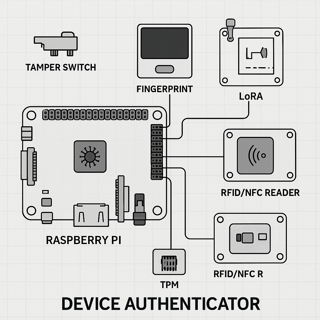
OTA Device Authenticator: Sensor Wiring and Driver Integration
1. GPS Module (u-blox NEO-6M)
Wiring (UART Serial to Raspberry Pi):
- GPS VCC → Pi 3.3V (Pin 1)
- GPS GND → Pi GND (Pin 6)
- GPS TX → Pi RXD (Pin 10 / GPIO15)
- GPS RX → Pi TXD (Pin 8 / GPIO14)
Python Driver: Use pyserial + pynmea2
import serial, pynmea2
ser = serial.Serial(“/dev/serial0”, 9600, timeout=1)
data = ser.readline()
if data.startswith(b”$GPGGA”):
msg = pynmea2.parse(data.decode())
print(msg.latitude, msg.longitude)
2. MLX90640 (Thermal Sensor)
Wiring (I2C):
- VIN → Pi 3.3V (Pin 1)
- GND → Pi GND (Pin 9)
- SDA → Pi SDA (Pin 3 / GPIO2)
- SCL → Pi SCL (Pin 5 / GPIO3)
Python Driver: Use Adafruit_MLX90640
import board, busio
import adafruit_mlx90640
i2c = busio.I2C(board.SCL, board.SDA, frequency=400000)
mlx = adafruit_mlx90640.MLX90640(i2c)
temp_frame = [0] * 768
mlx.getFrame(temp_frame)
print(f”Avg Temp: {sum(temp_frame)/len(temp_frame):.2f}C”)
3. USB Watchdog
Wiring: No external wiring, monitors via software
Python Driver:
import subprocess
output = subprocess.check_output(“lsusb”).decode()
print(“Devices:\n”, output)
4. RFID/NFC (PN532)
Wiring (I2C):
- SDA → Pi SDA (Pin 3)
- SCL → Pi SCL (Pin 5)
- VCC → Pi 3.3V (Pin 1)
- GND → Pi GND (Pin 6)
Python Driver: Use Adafruit_PN532
from adafruit_pn532.i2c import PN532_I2C
import board, busio
i2c = busio.I2C(board.SCL, board.SDA)
pn532 = PN532_I2C(i2c, debug=False)
uid = pn532.read_passive_target(timeout=0.5)
if uid:
print(“RFID Tag UID:”, [hex(i) for i in uid])
5. LoRa (RFM95 / SX127x)
Wiring (SPI):
- MISO → Pi MISO (Pin 21 / GPIO9)
- MOSI → Pi MOSI (Pin 19 / GPIO10)
- SCK → Pi SCLK (Pin 23 / GPIO11)
- NSS → Pi CE0 (Pin 24 / GPIO8)
- GND → Pi GND (Pin 25)
- VCC → Pi 3.3V (Pin 1)
Python Driver: Use pySX127x or lora-pi libraries with GPIO setup.
✅ Each of these sensor modules integrates with the /sensor/... endpoints from the API. You can swap the placeholder returns for real sensor values.*